![]()
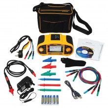
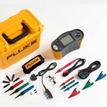
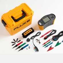
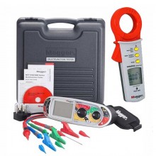
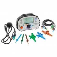
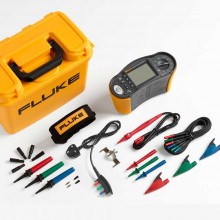
Includes: Metrel MI 3125BT COMBO PRO, Soft hand strap, Small soft carrying bag, Test lead, 3 x 1.5 m, Mains Plug Lead, Tip Commander, 1.5m, Test probe, 3 pcs (blue, brown, green), Crocodile clip, 3 pcs (blue, brown, green), Power supply adapter + 6 rechargeable batteries NiMH, type AA, USB cable, Metrel ES Manager BASIC license, Metrel aMESM PRO Android app, Short instruction manual, Calibration certificate.
 HTTPS Secure
Our pages are encrypted and protected from cyber-attack.
 Compliant
Payment Card Industry Data Security Standard (PCI DSS) Compliant.
 Protected
TLS (SSL) - all data/information is secure from interception.
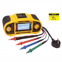
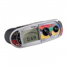
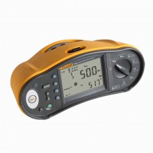
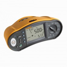
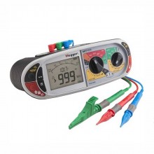
The Metrel MI 3125BT is the ideal instrument for engineers who perform high volume testing or work regularly on TT and TN systems. Containing all necessary tests for installation safety testing, MI 3125BT offers the brand new ability to test B-type (DC sensitive) RCDs. COMBO contains integrated characteristics of fuses and RCDs (including EV type) for the evaluation of line/loop impedance results.
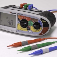
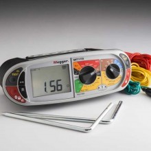
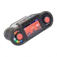
The bright graphic display with backlight ensures that results, indications, measurement parameters and messages are clear, visible and easy to read. The red and green LEDs on either side of the display provide a clear PASS/FAIL evaluation of test results. Each test has its own individual help screen describing how to connect the instrument into the installation and how to perform a measurement.
MEASURING FUNCTIONS
Insulation resistance with DC voltage.
Continuity of PE conductors with 200 mA test current with polarity change.
Continuity of PE conductors with 7 mA test current (continuous measurement) without RCD tripping.
Line impedance.
Loop impedance.
Loop impedance with Trip Lock RCD function.
TRMS voltage and frequency.
Phase sequence.
RCD testing (general and selective, type AC, A and B).
Earth resistance (3-wire method).
| Function | Measuring Range | Resolution | Accuracy |
| Insulation resistance (EN 61557-2) | U = 50, 100, 250 VDC: | ||
| R: 0.00 MΩ ... 19.99 MΩ | 0.01 MΩ | ±(5 % of reading + 3 digits) | |
| 20.0 MΩ ... 99.9 MΩ | 0.1 MΩ | ±10 % of reading. | |
| 100.0 MΩ ... 199.9 MΩ | 0.1 MΩ | ±20 % of reading. | |
| U = 500 VDC, 1 kVDC. | |||
| R: 0.00 MΩ ... 19.99 MΩ | 0.01 MΩ | ±(5 % of reading + 3 digits). | |
| 20.0 MΩ ... 99.9 MΩ | 0.1 MΩ | ±5 % of reading. | |
| 200 MΩ ... 999 MΩ | 1 MΩ | ±10 % of reading. | |
| Continuity 200 mA of PE conductor with polarity change (EN 61557-4) | 0.00 Ω ... 19.99 Ω | 0.01 Ω | ±(3 % of reading + 3 digits). |
| 20.0 Ω ... 199.9 Ω | 0.1 Ω | ±5 % of reading. | |
| 200 Ω ... 1999 Ω | 1 Ω | ±5 % of reading | |
| Loop impedance (EN 61557-3) | 0.00 Ω ... 9.99 Ω | 0.01 Ω | ±(5 % of reading + 5 digits) |
| 10.0 Ω ... 99.9 Ω | 0.1 Ω | ±(5 % of reading + 5 digits) | |
| 100 Ω ... 999 Ω | 1 Ω | ±10 % of reading | |
| 1.00 kΩ ... 9.99 kΩ | 10 Ω | ±10 % of reading | |
| Line impedance (EN 61557-3) | 0.00 Ω ... 9.99 Ω | 0.01 Ω | ±(5 % of reading + 5 digits) |
| 10.0 Ω ... 99.9 Ω | 0.1 Ω | ±(5 % of reading + 5 digits | |
| 100 Ω ... 999 Ω | 1 Ω | ±10 % of reading | |
| 1.00 kΩ ... 9.99 kΩ | 10 Ω | ±10 % of reading | |
| Voltage | 0 V ... 550 V | 1 V | ±(2 % of reading + 2 digits) |
| Frequency | 0.00 Hz ... 9.99 Hz | 0.01 Hz | ±(0.2 % of reading + 1 digits) |
| 10.0 Hz ... 499.9 Hz | 0.1 Hz | ||
| Phase sequence (EN 61557-7) | 1.2.3 or 3.2.1. | ||
| RCD testing (EN 61557-6) | ∆N: 10 mA, 30 mA, 100 mA, 300 mA, 500 mA, 1 A. | ||
| Contact voltage UC | 0.0 V ... 19.9 V | 0.1 V | (-0% / +15%) of reading ±10 d. |
| 20.0 V ... 99.9 V | 0.1 V | -0% / +15%) of reading. | |
| Trip-out time | 0 ms ... 40.0 ms | 0.1 ms | ±1 ms. |
| 0 ms ... max. time | 0.1 ms | ±3 ms. | |
| Trip-out current | 0.2 x I∆N ... 1.1 x I∆N (AC type) | 0.05 x I∆N | ±0.1 x I∆N. |
| 0.2 x I∆N ... 2.2 x I∆N (A type,∆N < 30 mA) | 0.05 x I∆N | ±0.1 x I∆N. | |
| 0.2 x I∆N ... 1.5 x I∆N (A type, I∆N ≥ 30 mA) | 0.05 x I∆N | ±0.1 x I∆N. | |
| 0.2 x I∆N ... 2.2 x I∆N (B type) | 0.05 x I∆N | ±0.1 x I∆N. | |
| Earth resistance (EN 61557-5) | 0.00 Ω ... 19.99 Ω | 0.01 Ω | ±(5 % of reading + 5 digits). |
| 20.0 Ω ... 199.9 Ω | 0.1 Ω | ±(5 % of reading + 5 digits). | |
| 200 Ω ... 9999 Ω | 1 Ω | ±(5 % of reading + 5 digits). | |
| General Specifications | |||
| Power supply | 6 x 1.5 V alcaline or 6 x 1.2 V rechargeable batteries, size AA. | ||
| Overvoltage category | 600 V / CAT III; 300 V / CAT IV. | ||
| Protection class | double insulation. | ||
| COM port | RS232 and USB. | ||
| Dimensions | 140 x 80 x 230 mm. | ||
| Weight | 1.0 kg. | ||
| Input voltage | 400 V (3-phase). |
| Frequency | 50 Hz. |
| Test current | 13 A. |
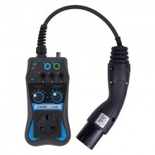
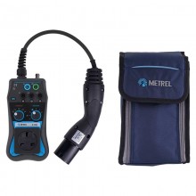
| Proximity Pilot (PP) simulation | Open circuit 13 A 20 A 32 A 63 A |
| Control Pilot (CP) simulation | State A (not connected) State B (connected, not charging) State C (charging without ventilation) State D (charging with ventilation) State E (error - CP short to PE via diode) |
| Overvoltage category | 300 V CAT II. |
| Protection degree | IP 40. |
| Pollution degree | 2. |
| Protection classification | Double insulation. |
| Altitude | 3000 m above sea level. |
| Dimensions (L x W x H) | 200 x 100 x 70 mm. |
| Test lead length | 0.5 m. |
| Weight | 0.82 kg. |
| Working temperature range | 0 °C … 40 °C @ 95 % RH, non-condensing |
| Storage temperature range | -10 °C … +70 °C. |
| Maximum storage relative humidity | 90 % RH (-10 °C … +40 °C) 80 % RH (40 °C … 60 °C). |
![]()
Includes: Metrel MI 3125BT COMBO PRO, Soft hand strap, Small soft carrying bag, Test lead, 3 x 1.5 m, Mains Plug Lead, Tip Commander, 1.5m, Test probe, 3 pcs (blue, brown, green), Crocodile clip, 3 pcs (blue, brown, green), Power supply adapter + 6 rechargeable batteries NiMH, type AA, USB cable, Metrel ES Manager BASIC license, Metrel aMESM PRO Android app, Short instruction manual, Calibration certificate.