![]()
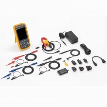
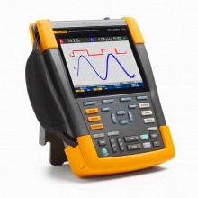
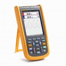
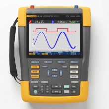
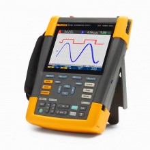
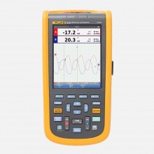
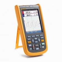
Includes: Fluke 190-202-III with Handstrap, Hangstrap, BC190/830 Power Adapter/Charger, Universal Power Cord Set, BP290 Li-ion Battery, TL175 Test Lead Set, 2x VPS421-x Ruggedized Voltage Probe, USB interface cable for PC connection (USB-A to mini-USB-B), Safety Information, FlukeView 2 Demo Software. Included items may vary based on model selected.
 HTTPS Secure
Our pages are encrypted and protected from cyber-attack.
 Compliant
Payment Card Industry Data Security Standard (PCI DSS) Compliant.
 Protected
TLS (SSL) - all data/information is secure from interception.
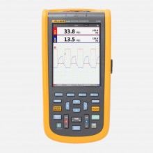
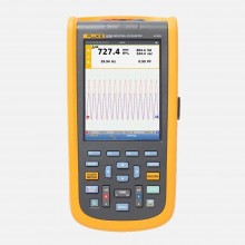
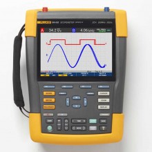
The Fluke 190 Series III ScopeMeter Test Tools are engineered to go where you go, and tackle just about any troubleshooting job along the way. These CAT III 1000 V/CAT IV 600V rated test tools combine rugged portability with the high performance of bench oscilloscopes to help you take on the challenges of installing, commissioning and maintaining industrial machinery, automation and process controls, and power conversion electronics with ease - from DC to 500 MHz.
Choose from two or four channel models with a wide range of bandwidth options. Fast sampling rates up to 5.0 GS/s, 200 ps resolution and deep memory of 10,000 samples per channel allow high-accuracy capture and display of waveform details, noise, and other disturbances. Perform timing or amplitude related measurements on three phases or three-axis control systems, or simply compare and contrast multiple test points in a circuit under test.
NB: The FLUKE-190-202-III-S Kit version (selectable from the dropdown above) comes complete with a CXT293 carrying case, FlukeView®-2 PC-Software activation key, D-Link DWA-131 Wi-Fi dongle.
FEATURES
Rated for industrial environments CAT III 1000 V/CAT IV 600 V.
Automatically capture, view and analyse complex waveforms.
Up to four independent floating isolated inputs, up to 1000 V.
Up to 5 GS/s real time sampling (depending on model and channels used).
Deep memory: 10,000 points per trace waveform capture (scope mode).
5,000 count DMM included in the 2-channel models.
IP51 rating, dust and drip-proof.
Large, bright colour display for easy in-the-field viewing.
USB and Wi-Fi download for analysing data with FlukeView® software.
| Oscilloscope Modes | |||||||
| - | 190-062 | 190-102 | 190-202 | 190-502 | 190-104 | 190-204 | 190-504 |
| Vertical deflection | |||||||
| Number of channels | >2 | >2 | >2 | >2 | >4 | >4 | >4 |
| Bandwidth | >60 MHz | >100 MHz | >200 MHz | >500 MHz | >100 MHz | >200 MHz | >500 MHz |
| Rise time | >5.8 ns | >3.5 ns | >1.7 ns | >0.7 ns | >3.5 ns | >1.7 ns | >0.7 ns |
| Number of scope inputs | 2 input channels plus external trigger | 4 input channels | |||||
| Channel architecture | All inputs fully insulated from each other and from ground. Inputs may be activated in any combination. | ||||||
| Input coupling | AC or DC, with ground level indicator. | ||||||
| Input sensitivity | With 10:1 probe, 20 mV to 1000 V/div With 100:1 probe, 200 mV to 10 kV/div Direct (1:1), 2 mV to 100 V/div. |
||||||
| Bandwidth limiter | 20 MHz and 10 kHz. | ||||||
| Polarity | Normal, Inverted, Variable. | ||||||
| Input voltage | CAT III 1000 V/CAT IV 600 V rated, see General specifications for further details. | ||||||
| Vertical resolution | 8 bit. | ||||||
| Accuracy at 4 s to 10 μs/div |
5 mV/div to 100 V/div, ±(1.5 % + 6 counts) 2 mV/div, ±(1.5 % + 10 counts). |
||||||
| Input impedance | 1 MΩ (± 1 %) // 15 pF (± 2.25 pF). | ||||||
| Horizontal | |||||||
| - | 190-062 | 190-102 | 190-202 | 190-502 | 190-104 | 190-204 | 190-504 |
| Maximum real-time sample rate (sampled simultaneously) |
>625 MS/s (each channel) |
>1.25 GS/s (each channel) | >2.5 GS/s (each channel) | >5 GS/s (single channel) or 2.5 GS/s (dual channel) |
>1.25 GS/s (each channel) | >2.5 GS/s (2ch) 1.25 GS/s (4ch) |
>5 GS/s (single ch) or 2.5 GS/s (2ch) or 1.25 GS/s (4ch) |
| Record length | Up to 10,000 samples per channel. | ||||||
| Time base range | >10 ns/div to 4 s/div |
>5 ns/div to 4 s/div |
>2 ns/div to 4 s/div |
>1 ns/div to 4 s/div |
>5 ns/div to 4 s/div |
>2 ns/div to 4 s/div |
>1 ns/div to 4 s/div |
| Maximum record length | 10,000 samples per channel in scope mode. 30,000 points per channel in ScopeRecord™ Roll mode (see ‘Recorder mode’). |
||||||
| Timing accuracy | ± (0.01 % of reading + 1 pixel). | ||||||
| Glitch capture | 8 ns (10 µs/div to 2 min/div). | ||||||
| Display and acquisition | |||||||
| Display | 133 mm x 90 mm (5.3 in x 3.5 in) full-colour high brightness LCD. | ||||||
| Display modes | Any combination of channels; average on/off; replay. | ||||||
| Visible screen width | 12 divisions horizontally in scope mode. | ||||||
| Digital persistence modes | Off, short, medium, long, infinite and envelope mode. | ||||||
| Waveform mathematics | One (190-xx2) or two (190-x04) mathematical operations on 2 input channels (A and B, C and D): add, subtract, multiply; X-Y-mode; Frequency Spectrum using FFT. | ||||||
| Acquisition modes | Normal, Averaged, Auto, Single Shot, ScopeRecord™ roll, glitch capture, waveform compare with automatic “Pass/Fail testing”; Replay. | ||||||
| Trigger and delay | |||||||
| Source | Input A, B or External (via meter input) | Input A, B, C or D | |||||
| Modes | Automatic, Edge, Pulse Width, N-Cycle, External (190-xx2). | ||||||
| Connect-and- View™ | Advanced automatic triggering that recognizes signal patterns, automatically sets up and continuously adjusts triggering, time base and amplitude. Automatically displays stable waveforms of complex and dynamic signals like motor drive and control signals. Can be switched off if preferred. | ||||||
| Pulse width triggering (on channel A) | Pulse width qualified by time Allows for triggering <t, >t, =t, ≠ t, where t is selectable in minimum steps of 0.01 div or 50 ns. |
||||||
| Time delay | 1 full screen of pre-trigger view or up to 100 screens (=1,200 divisions) of post-trigger delay. | ||||||
| Dual slope triggering | Triggers on both rising and falling edges alike. | ||||||
| N-cycle triggering | Triggers on N-th occurrence of a trigger event; N to be set in the range 2 to 99. | ||||||
| Automatic capture of 100 screens | |||||||
| When in oscilloscope mode, the instrument ALWAYS memorizes the last 100 screens—no specific user setup required. When an anomaly is seen, the REPLAY button can be pressed to review the full sequence of screen events over and over. Instrument can be set up for triggering on glitches or intermittent anomalies and will operate in “baby-sit” mode capturing 100 specified events. | |||||||
| Replay | Manual or continuous replay. Displays the captured 100 screens as a “live” animation, or under manual control. Each screen has date and time-stamp. | ||||||
| Replay storage | Ten sets of 100 screens each can be saved internally for later recall and analysis. Direct storage of additional sets on external flash memory drive through USB host port. | ||||||
| FFT—frequency spectrum analysis | |||||||
| Shows frequency content of oscilloscope waveform using Fast Fourier Transform. | |||||||
| Window | Automatic, Hamming, Hanning or None. | ||||||
| Automatic window | Digitally re-samples acquired waveform to get optimum frequency resolution in FFT resultant. | ||||||
| Vertical scale | Linear/Logarithmic (in volts or amps). | ||||||
| Frequency axis | Frequency range automatically set as a function of timebase range of oscilloscope. | ||||||
| Waveform compare and pass/fail testing | |||||||
| Waveform compare | Provides storage and display of a reference waveform for visual comparison with newly acquired waveforms. Reference is derived from an acquired waveform and can be modified in the oscilloscope. | ||||||
| Pass/Fail testing | In waveform compare mode, the oscilloscope can be set up to store only matching (“Pass”) or only non-matching (“Fail”) acquired waveforms in the replay memory bank for further analysis. | ||||||
| Automatic scope measurements | |||||||
| V dc, V ac rms, V ac+dc, Vpeak max, Vpeak min, Vpeak to peak, A ac, A dc, A ac+dc, frequency (in Hz), rise time (using cursors), fall time (using cursors), Power Factor (PF), Watts, VA, VA reactive, phase (between 2 inputs A&B or C&D), pulse width (pos./neg.), duty cycle (pos./ neg.), temperature °C, temperature °F (not for Japan), dBV, dBm into 50 Ω and 600 Ω, VPWM ac and VPWM(ac+dc) for measurement on pulse width modulated motor drives and frequency inverters, V/Hz ratio; | |||||||
| Advanced power and motor drive functions | V/Hz ratio, Power Factor (PF), Watts, VA, VA reactive, V-PWM (ac) and V-PWM (ac+dc) for measure- ment on pulsewidth modulated motordrives and frequency inverters. | ||||||
| Cursor measurements | |||||||
| Source | On any input waveform or on mathematical resultant waveform (excl. X-Y-mode). | ||||||
| Dual horizontal lines | Voltage at cursor 1 and at cursor 2, voltage between cursors. | ||||||
| Dual vertical lines | Time between cursors, 1/T between cursors (in Hz), voltage between markers, risetime with markers, falltime with markers; Vrms between cursors, Watts between cursors. | ||||||
| Single vertical line | Min-Max and Average voltage at cursor position; frequency and rms-value of individual frequency component in the FFT Resultant. | ||||||
| Advanced functions | mA*s (current-over-time, between cursors); V*s (voltage-over-time, between cursors); W*s (energy, between cursors). | ||||||
| ZOOM | Ranges from full record overview to zoom in up to sample level, at any record length. | ||||||
| Meter modes | |||||||
| - | 190-062 | 190-102 | 190-202 | 190-502 | 190-104 | 190-204 | 190-504 |
| Meter inputs | Via 4 mm banana inputs, fully isolated from scope inputs and scope ground. | Via BNC scope inputs. | |||||
| Number of readings | One at a time via DMM input. | Up to 4 automatic scope measurements simultaneously. | |||||
| Maximum resolution | 5,000 counts. | ± 999 counts (frequency: 9999 counts). |
|||||
| Input impedance | 1 MΩ (± 1 %) // 14 pF (± 1.5 pF). | 1 MΩ (± 1 %) // 15 pF (± 2.25 pF). | |||||
| Advanced meter functions | Auto/manual ranging, relative measurements (Zero reference), TrendPlot™ recording. | ||||||
| - | The specified accuracy is valid over the temperature range 18 °C to 28 °C Add 10 % of specified accuracy for each degree C below 18 °C or above 28 °C. | ||||||
| Voltage | |||||||
| V dc accuracy | ± (0.5 % + 6 counts). | ± (1.5 % + 6 counts). | |||||
| V ac true rms accuracy | |||||||
| 15 Hz to 60 Hz | ± (1 % + 10 counts). | ± (1.5 % + 10 counts). | |||||
| 60 Hz to 1 kHz | ± (2.5 % + 15 counts). | — | |||||
| 60 Hz to 20 kHz | — | ± (2.5 % + 15 counts). | |||||
| V ac+dc true rms accuracy | |||||||
| 15 Hz to 60 Hz | ± (1 % + 10 counts). | ± (1.5 % + 10 counts). | |||||
| 60 Hz to 1 kHz | ± (2.5% + 15 counts). | — | |||||
| 60 Hz to 20 kHz | — | ± (2.5 % + 15 counts). | |||||
| Voltmeter ranges | 500 mV, 5 V, 50 V, 500 V, 1,100 V. | ||||||
| Resistance | |||||||
| Ranges | 500 Ω, 5 kΩ, 50 kΩ, 500 kΩ, 5 MΩ, 30 MΩ. | — | |||||
| Accuracy | ± (0.6 % + 6 counts). | — | |||||
| Other meter functions | |||||||
| Continuity | Beeper on < 50 Ω (± 30 Ω). | — | |||||
| Diode test | Up to 2.8 V. | — | |||||
| Current (A) | A dc, A ac, A ac+dc using an optional current clamp or shunt Scaling factors: 0.1 mV/A, 1 mV/A to 100 V/A and 400 mV/A. | ||||||
| Temperature | With optional accessories. Scale factors 1mV/°C or 1mV/°F. | ||||||
| Recorder mode | |||||||
| 190-062 | 190-102 | 190-202 | 190-502 | 190-104 | 190-204 | 190-504 | |
| ScopeRecord™ Roll Mode | |||||||
| Dual or multiple input waveform storage mode, using deep memory. | |||||||
| Source and display | Input A, Input B, Dual All channels sampled simultaneously Any combination of inputs, up to 4 channels. All channels sampled simultaneously. |
||||||
| Memory depth | 30,000 data points per channel, each holding min/max pair of information. | ||||||
| Min/max values | Min/max values are created at samples that are measured at high sample rate ensuring capture and display of glitches. | ||||||
| Recording modes | Single sweep, continuous roll; Start-on-Trigger (through external); Stop-on-Trigger (through external). | Single sweep, continuous roll; Start-on-Trigger (through any channel); Stop-on-Trigger (through any channel). | |||||
| Stop-on-trigger | ScopeRecord mode can be stopped by an individual trigger event, or by an interruption of a repetitive trigger signal, through any input channel (through External on 190-XX2 Series). |
||||||
| Horizontal scale | Time from start, time of day. | ||||||
| Zoom | Ranges from full record overview to zoom in up to sample level. | ||||||
| Memory | Two multiple input ScopeRecord waveforms can be saved internally for later recall and analysis. | ||||||
| ScopeRecord™ Roll mode sample rate and recording timespan | |||||||
| Time base range | 4 ms/div to 2 min/div. | ||||||
| Recorded timespan | 4.8 sec to 40 hr. | ||||||
| Time/division in ‘view all’ mode | 0.4 s/div to 4 h/div. | ||||||
| Glitch capture | 8 ns. | ||||||
| Sample rate | 125 MS/s. | ||||||
| Resolution | 160 μsec ~ 4.8 sec. | ||||||
| Trendplot™ Recording | |||||||
| Multiple channel electronic paperless recorder. Graphically plots, displays and stores results of up to four automatic scope measurements or a DMM-reading over time. | |||||||
| Source and display | Any combination of scope measurements, made on any of the input channels, or DMM reading (2-channel instruments). | ||||||
| Memory depth | 19,200 points (sets) per recording. Each recorded sample point contains a minimum, a maximum and an average value, plus a date- and time-stamp. | ||||||
| Ranges | Normal view: 5 s/div to 30 min/div; In view-all mode: 5 min/div to 48 hr/div (overview of total record). | ||||||
| Recorded time span | Up to 22 days, with a resolution of 102 seconds; up to 5.5 days for 4 readings. | ||||||
| Recording mode | Continuous recording, starting at 5 s/div with automatic time-scale compression. | ||||||
| Measurement speed | Three automatic measurements per second or more. | ||||||
| Horizontal scale | Time from start, time of day. | ||||||
| Zoom | Up to 64x zoom-out for full record overview, up to 10x zoom-in for maximum detail. | ||||||
| Memory | Two multiple input TrendPlot records can be saved internally for later recall and analysis. | ||||||
| Cursor measurements—all recorder modes | |||||||
| Source | Any waveform trace in any waveform display mode (Scope, ScopeRecord or TrendPlot). | ||||||
| Dual vertical lines | Cursors may be used to identify Min, Max or Average value of any datapoint in a record, with time between cursors, time from start or absolute time. | ||||||
| General Specifications | |||||||
| Input voltage range | |||||||
| Rated maximum floating voltage | CAT III 1000 V / CAT IV 600 V (maximum voltage between any contact and earth-ground voltage level). | ||||||
| Probe input voltage VPS410-II | CAT III 1000 V / CAT IV 600 V (Maximum voltage between standard 10:1 probe tip and reference lead). | ||||||
| Probe input voltage VPS421 | CAT III 1000V / CAT IV 600V (Maximum voltage between probe tip or reference lead to GND, 2000V max between probe tip and reference lead). | ||||||
| Maximum BNC input voltage | CAT IV 300 V (maximum voltage on BNC input directly). | ||||||
| Maximum volt- age on meter input | CAT III 1000 V / CAT IV 600 V (safety designed banana input connectors). |
— | |||||
| Memory save and recall | |||||||
| Memory loca- tions (internal) | 30 waveform memories plus 10 recording memories plus 9 screen copy memories. | ||||||
| 30 waveform memories | Each memory can contain up to 2 or 4 waveforms plus corresponding setups. | ||||||
| 10 recording memories | Each may contain: a 100 Screen Replay sequence, or a ScopeRecord Roll-mode recording (2 or 4 traces), or a TrendPlot recording of up to 4 measurements. | ||||||
| External data storage | On PC, using FlukeView™-2 Software, or direct storage on external flash memory drive (maximum 32 GB) through USB host port. | ||||||
| Screencopies | On PC, using FlukeView™-2 Software, or internally (in instrument) which can be copied on to external flash memory drive as .BMP-file, through USB host port. | ||||||
| Volatility | Saving is done in non-volatile Flash-ROM and all data is secured, independent of battery or power status. | ||||||
| Real-time clock | Provides date and time stamp information for ScopeRecord, for 100 Screen Replay sequences and for TrendPlot recordings. | ||||||
| Case | |||||||
| Design | Rugged, shock-proof with integrated protective holster. Handstrap and hangstrap included as standard. Kensington lock supported to lock down instrument when left unattended. |
||||||
| Drip and dust proof | IP 51 according to IEC60529. | ||||||
| Shock and vibration | Shock 30 g, vibration (sinusoidal) 3 g / 0.03 g2/Hz (Random), according to MIL-PRF-28800F Class 2. | ||||||
| Display size | 133 mm x 90 mm (5.3 in x 3.5 in) LCD. | ||||||
| Resolution | 1120 pixels x 765 pixels. | ||||||
| Brightness | User-adjustable, up to 300 cd/m2. | ||||||
| Mechanical data | |||||||
| Size | 265 mm x 192 mm x 70 mm (10.5 in x 7.6 in x 2.8 in). | ||||||
| Weight (including battery) | 2.1 kg (4.6 lb). | 2.2 kg (4.8 lb). | |||||
| Power | |||||||
| Line power | Universal mains adapter/battery charger BC190/830 included, with detachable 2-wire power cords 100 Vac to 240 Vac, ±10 %, 50-60 Hz. | ||||||
| .Battery power | Re-chargeable Li-Ion battery (included). Battery swappable through easily accessible battery door at the rear of the instrument. | ||||||
| Battery type (incl.) and capacity [+opt. battery] | BP290: 10.8V, 2500 mAh [BP291 (5000 mAh) optional] |
BP291: 10.8V, 5000 mAh. | |||||
| Battery charge indicator | Battery has built-in status indicator for use with external charger, next to battery status indicator on instrument screen. | ||||||
| Battery operat- ing time (with backlight low) | Up to 3.5 using BP290 (included), up to 7 hours using BP291 (optional). | Up to 7 hours using BP291 (included) | |||||
| Battery charging time | 2½ hours using BP290; 5 hours using BP291 | Five hours for BP291.. | |||||
| Battery power saving functions | Auto ‘power down’ with adjustable power down time. Automatic ‘display off’ with adjustable power down time. On-screen battery power indicator. |
||||||
| Safety | |||||||
| Compliance | EN61010-1, Pollution Degree 2; IEC 61010-2-030: CAT IV 600 V / CAT III 1000 V. |
||||||
| Environmental | |||||||
| Operating temperature | Battery discharging: 0 °C to 40 °C (32 °F to 104 °F) Battery charging: 0 °C to 40 °C (32 °F to 104 °F). |
||||||
| Storage temperature | -20 °C to 60 °C (-4 °F to 140 °F). | ||||||
| Humidity | 0 °C to 10 °C (32 °F to 50 °F): noncondensing 10 °C to 30 °C (50 °F to 86 °F): 95 % (±5 %) 30 °C to 40 °C (86 °F to 104 °F): 75 % (±5 %) 40 °C to 50 °C (104 °F to 122 °F): 45 % (±5 %). |
||||||
| Maximum operating altitude | CAT IV 600 V, CAT III 1000 V: up to 2000 m (6 600 feet) CAT IV 300 V, CAT III 600 V, CAT II 1000 V: up to 4000 m (13 000 feet). |
||||||
| Maximum storage altitude | 12 km (40,000 ft). | ||||||
| Electro-Magnetic Compatibility (EMC) | IEC 61326-1: Industrial; CISPR 11: Group 1, Class A; Korea (KCC): Class A Equipment (Industrial Broadcasting and Communication Equipment); USA (FCC): 47 CFR 15 subpart C. |
||||||
| Interfaces | Two USB-ports provided. Ports are fully insulated from instrument’s floating measurement circuitry. USB-host port directly connects to external flash memory drive (up to 32 GB) for storage of waveform data, measurement results, instrument settings and screen copies. Alternatively, this USB-A port may be used to connect a WiFi Adapter for wireless PC connectivity. A mini-USB-B is provided which allows for interconnection to PC for remote control and data transfer under PC-control using FlukeView-2. |
||||||
| Probe calibration output | Dedicated probe-cal output with reference contact provided, fully insulated from any measurement input channel. Generator Output: 1.225 Vpp / 500 Hz square wave. |
||||||
| Warranty | 3 years on main instrument, 1 year on battery and accessories. | ||||||
| COMPONENT |
DESCRIPTION | PART No. | ||
| BC190 | Mains adapter/battery charger. | 4821057 | ||
| BP290 | Li-ion battery pack, 2500 mAh. | 4025762 | ||
| BP291 | Li-ion battery pack, 5000 mAh. | 3894688 | ||
| HH290 | Hanging Hook for 190 Series II and III instruments. | 3894844 | ||
| VPS510-R | Electronic Voltage Probe set, 10:1, 500 MHz, one set red. | 4025781 | ||
| VPS510-G | Electronic Voltage Probe set, 10:1, 500 MHz, one set grey. | 4025801 | ||
| VPS510-B | Electronic Voltage Probe set, 10:1, 500 MHz, one set blue. | 4025796 | ||
| VPS510-V | Electronic Voltage Probe set, 10:1, 500 MHz, one set green. | 4025812 | ||
| VPS410-II-G | Industrial Voltage Probe set, 10:1, one set grey. | 4276943 | ||
| VPS410-II-R | Industrial Voltage Probe set, 10:1, one set red. | 4276928 | ||
| VPS410-II-B | Industrial Voltage Probe set, 10:1, one set blue. | 4276937 | ||
| VPS410-II-V | Industrial Voltage Probe set, 10:1, one set green. | 4276955 | ||
| TL175 | TwistGuard™ safety designed test leads set (1 red, 1 black). | 3521976 | ||
| TRM50 | BNC Feedthrough 50 Ω terminator (set of 2 pieces, black). | 4025864 | ||
| AS400 | Probe Accessory Extension Set for VPS410-series probes. | 38944880 | ||
![]()
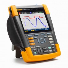
Includes: Fluke 190-202-III with Handstrap, Hangstrap, BC190/830 Power Adapter/Charger, Universal Power Cord Set, BP290 Li-ion Battery, TL175 Test Lead Set, 2x VPS421-x Ruggedized Voltage Probe, USB interface cable for PC connection (USB-A to mini-USB-B), Safety Information, FlukeView 2 Demo Software. Included items may vary based on model selected.